Part 1.
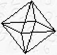
Students make straw octahedrons (see http://math.nmsu.edu/breakingaway/Lessons/straw/straw.html). They should use three different colors of straws to show that a regular octahedron is built from three mutually perpendicular squares. (The quality of the work counts!)The instructor shows a shadow of the octahedron on a screen using a projector. The shadow should not be too big to avoid distortion due to perspective. The instructor talks about rotations around three axes: horizontal parallel to the screen (x axis), vertical parallel to the screen (y axis), and perpendicular to the screen (z axis).
Any rotation in space can be obtained by composition of these three rotations.
Part 2.
Students write and use a program for the TI-83 Plus, which simulates movements of the shadow on a screen when an octahedron is rotated in space.Data structures (representation of an octahedron, namely, its vertices and edges, and matrices representing rotations).
Vertices of an octahedron, in an initial position, stored in a 3 by 6 matrix [I].
[[9 -9 0 0 0 0] ← x coordinates
[I] = [0 0 9 -9 0 0] ← y coordinates
[0 0 0 0 9 -9]] ← z coordinates
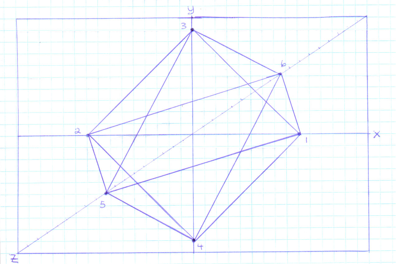
You can see below how these six points can be connected in a 2-d plane to form a 2-d projection of an octahedron.
Edges stored in a 2 by 12 matrix [J] in the order: top 4, bottom 4, and horizontal square.
[[5 5 5 5 6 6 6 6 3 3 4 4]
[J] = [1 2 3 4 1 2 3 4 1 2 1 2]]
Students should draw a (fairly large) octahedron, label its vertices, and identify all its edges.
Rotations by angles A, B, and C, stored in 3 by 3 matrices [A], [B], and [C].
[[1 0 0 ] rotation around x axis,
[A] = [0 cos(A) -sin(A)] x coordinates don't change,
[0 sin(A) cos(A)]] y and z change.
[[cos(B) 0 -sin(B)] rotation around y axis,
[B] = [0 1 0 ] y coordinates don't change,
[sin(B) 0 cos(B)]] x and z change.
[[cos(C) -sin(C) 0] rotation around z axis,
[C] = [sin(C) cos(C) 0] z coordinates don't change,
[ 0 0 1]] x and y change.
PROGRAM:OCTAHEDR
:While 1
:[A][I]->[I]
:ClrDraw
:prgmDRAW
:Pause
:[B][I]->[I]
:ClrDraw
:prgmDRAW
:Pause
:[C][I]->[I]
:ClrDraw
:prgmDRAW
:Pause
:End
You may use the matrix editor to enter [I], [J] and [A], [B], and [C] for specific values
of angles A, B, C, (for example 11, 13 and 17 degrees) and observe rotations.
Remark.
Students should use their straw models to see which position of an octahedron
is represented on the calculator's display.
But if they want to study what happens when angles A, B, and C change, it is better to
create matrices [A], [B], and [C] using a program.
| Drawing program. | Explanation |
| PROGRAM:MATRICES | |
:[[1,0,0][0,cos( A),-sin(A)][0,si n(A),cos(A)]]→[A ]:[[cos(B),0,-si n(B)][0,1,0][sin (A),0,cos(B)]]→ [ B]:[[cos(C),-sin (B),0][sin(C),co s(C),0][0,0,1]]→ [C]:"DONE" |
This program creates matrices [A], [B], and [C], and displays the word DONE. |
Now in order to change the angles, just assign new values to these you want to change and run prgmMATRICES.